Optical Signaling Circuit
Objective
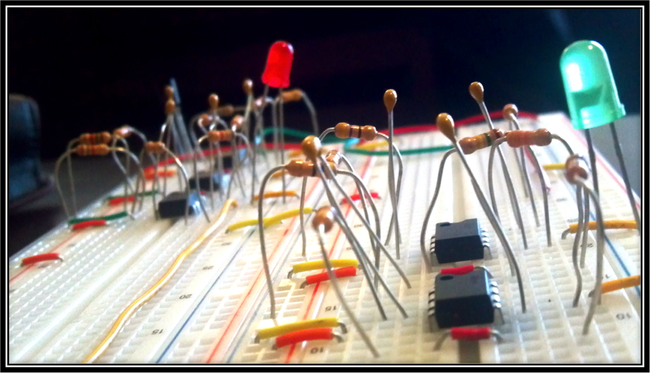
The objective of this final design project was to build a simple circuit that would light one light when one switch is closed, and a second light when the other switch is closed. The optical signal will be transmitted wirelessly from an inferred LED to a photo diode. With filters connected to the output of the photo diode receiver, the signal will activate one of the two lights to turn on, depending on the frequency of the optical signal.
Reflection
I personally had a lot of fun working on this final project. When we completed the circuit, it was great to activate the switch to see the lights on the other side turn on and off. This project really makes you have an appreciation for how TV remote controls function. After completing the circuit, I wish we had more time to really dial in and perfect our project. One flaw in our design is that our high pass filter would only light the LED within a certain range between the photo diode and the transmission LED. We could have fixed this issue by having a stronger current through the infrared LED and/or attaching more infrared LEDs to transmit twice the signal. This high pass filter also had the issue of outputting 9k Hz when a 1k Hz frequency was inputted. Thankfully, the amplitude was so low at that point that the LED would not light. I would have liked to alter this frequent issue.
If I were to do this project again, I would design precise band pass filters instead of low pass and high pass filters. The band pass filters would make sure only the correct frequencies were making it through, and it would be more precise. I would also make a full wave rectifier to make the signal DC. The full wave rectifier circuit would create a constant DC voltage output that we would use to power our LEDs in the circuit. The way our project was designed, the LEDs are basically blinking so fast that it looks like they are just a bright constant light. This is not a well-designed plan because according to the LEDs specifications, they have a limited number of times to blink before they stop working. The constant DC voltage (or a small rippled waveform) would prevent this from happening so that the LEDs would have a much longer life.
Project Documentation
https://www.scribd.com/doc/119212699/EE-230-Remote-Receiver